

In the rapidly expanding world of fiber optic networks, where bandwidth demands are skyrocketing due to 5G, FTTH (Fiber to the Home), cloud computing, and hyperscale data centers, the fiber optic PLC splitter has become an indispensable passive component. Also known as PLC splitter, fiber PLC splitter, or optical PLC splitter, this device efficiently divides a single optical signal into multiple outputs, enabling cost-effective distribution in PON (Passive Optical Network) architectures.
As of January 2026, with global FTTH connections exceeding 2.5 billion and next-generation PON technologies like 50G-PON and 100G-PON gaining traction, the fiber optic PLC splitter is more critical than ever. Popular configurations such as the 1×2 PLC splitter, 1×4 PLC splitter, 1×8 PLC splitter, 1×16 PLC splitter, 1×32 PLC splitter, and 1×64 PLC splitter are deployed in millions of networks worldwide, supporting everything from residential broadband to enterprise and telecom backbone systems.
This comprehensive guide explores every aspect of the fiber optic PLC splitter in 2026: its definition and working principle, historical evolution, detailed construction and manufacturing process, exhaustive classification of types and configurations (with emphasis on 1×2 PLC splitter, 1×4 PLC splitter, 1×8 PLC splitter, 1×32 PLC splitter, 1×64 PLC splitter, and more), key performance specifications and industry standards, real-world applications across industries, how to choose the right PLC splitter for your project, quality control and testing requirements, common myths and misconceptions, and practical procurement strategies.
1. What Is a Fiber Optic PLC Splitter? Definition, Purpose, and Fundamental Role
A fiber optic PLC splitter (Planar Lightwave Circuit splitter) is a passive optical device that divides a single input optical signal into multiple output signals with minimal loss and high uniformity. It is based on planar waveguide technology, where light is guided and split through lithographically patterned waveguides on a silica substrate.
1.1 Core Functions of the PLC Splitter
- Signal Splitting: Distributes optical power from one input fiber to 2, 4, 8, 16, 32, 64, or more outputs. For example, a 1×8 PLC splitter divides power to 8 outputs, a 1×32 PLC splitter to 32, and a 1×64 PLC splitter to 64.
- Low Insertion Loss: Typical values range from 3.5 dB for a 1×2 PLC splitter to 20 dB for a 1×64 PLC splitter.
- High Uniformity: Ensures even power distribution across outputs, critical for consistent service quality.
- Bidirectional Operation: Works for splitting in downstream and combining in upstream (e.g., in PON).
- Passive Design: No power required, zero maintenance, high reliability.
Itu optical PLC splitter is the preferred choice over fused biconical taper (FBT) splitters for modern networks due to superior uniformity, wavelength independence (1260–1650 nm), and temperature stability.
1.2 Why PLC Splitters Are Essential in 2026
- FTTH Explosion: Billions of homes require cost-effective splitting from OLT to ONT, with 1×32 PLC splitter Dan 1×64 PLC splitter enabling high-split ratios.
- High-Speed PON: 50G/100G PON demands low-loss, high-uniformity fiber PLC splitters.
- Data Center Monitoring: 1×2 PLC splitter Dan 1×4 PLC splitter for tap monitoring.
- 5G Fronthaul: Compact PLC splitters for distributed antenna systems.
- Cost Efficiency: One fiber serves dozens of users, reducing infrastructure expense.
A single poor-quality fiber optic PLC splitter can cause uneven power distribution, leading to dropped connections or degraded service for multiple users.
1.3 Historical Evolution of PLC Splitters
- 1990s: Early FBT splitters dominate; PLC technology emerges in research labs as a more precise alternative.
- Early 2000s: PLC commercialized for telecom; 1×8 PLC splitter becomes standard for GPON (up to 8 homes per fiber).
- 2010s: Mass production drives costs down; 1×32 PLC splitter Dan 1×64 PLC splitter enable larger PON splits (32–64 homes).
- 2020s: Miniaturized bare fiber and blockless PLC; ABS box and rack-mount for diverse deployments; ultra-low-loss versions for 50G-PON.
The shift from FBT to PLC has been driven by superior performance in high-split-ratio, wavelength-independent networks.
2. How Fiber Optic PLC Splitters Work: Technology and Construction
2.1 Planar Lightwave Circuit Technology
Itu PLC splitter uses semiconductor fabrication techniques similar to integrated circuits:
- A silica substrate serves as the base.
- Waveguides are patterned via photolithography and etching.
- Input light splits through Y-branch structures (for low ratios like 1×2 PLC splitter, 1×4 PLC splitter) or multimode interference (MMI) couplers (for higher ratios like 1×32 PLC splitter, 1×64 PLC splitter).
This planar approach ensures precise control over splitting ratios, wavelength independence (1260–1650 nm typical), and low polarization-dependent loss (PDL).
2.2 Detailed Construction of a PLC Splitter
- PLC Chip: The core waveguide structure on silica wafer, diced into individual chips.
- Input/Output Fibers: Ribbon or single fibers attached to chip using V-groove arrays for precise alignment.
- Packaging Options:
- Bare Fiber PLC Splitter: Chip only; lowest cost, for splicing.
- Blockless/Mini Module: Small steel tube protection; compact for tight spaces.
- ABS Box PLC Splitter: Rugged plastic cassette with connectors; most popular for FTTH.
- LGX/Rack-Mount: Metal module for ODF integration.
- Cassette/Tray: Slide-in for patch panels.
2.3 Manufacturing Process Step by Step
- Wafer fabrication with silica deposition.
- Photolithography to pattern waveguides.
- Etching and doping for light guidance.
- Dicing into individual chips.
- Fiber array attachment with UV epoxy.
- Packaging (tube, box, etc.).
- 100% testing for insertion loss, uniformity, return loss.
Dekam Fiber uses advanced lithography for uniformity <0.5 dB across all outputs, even in 1×64 PLC splitter configurations.
2.4 Comparison with FBT Splitters
While FBT (fused biconical taper) splitters are cheaper for low ratios like 1×2 PLC splitter equivalents, PLC offers:
- Better uniformity (±0.5 dB vs ±1.0 dB)
- Wavelength independence
- Temperature stability (–40°C to +85°C)
- Higher split ratios (up to 1×128)
PLC is the industry standard for all modern deployments.
3. Comprehensive Types and Configurations of PLC Splitters
Fiber PLC splitters are classified by split ratio, packaging, connector type, and fiber type.
3.1 By Split Ratio (Most Common Configurations)
The split ratio determines how many outputs one input fiber serves:
- 1×2 PLC Splitter: Basic building block; low loss (~3.5 dB); used for redundancy, monitoring, or small networks.
- 1×4 PLC Splitter: Entry-level for small MDUs or enterprises; loss ~7 dB.
- 1×8 PLC Splitter: Standard for early GPON; serves 8 homes; loss ~10 dB.
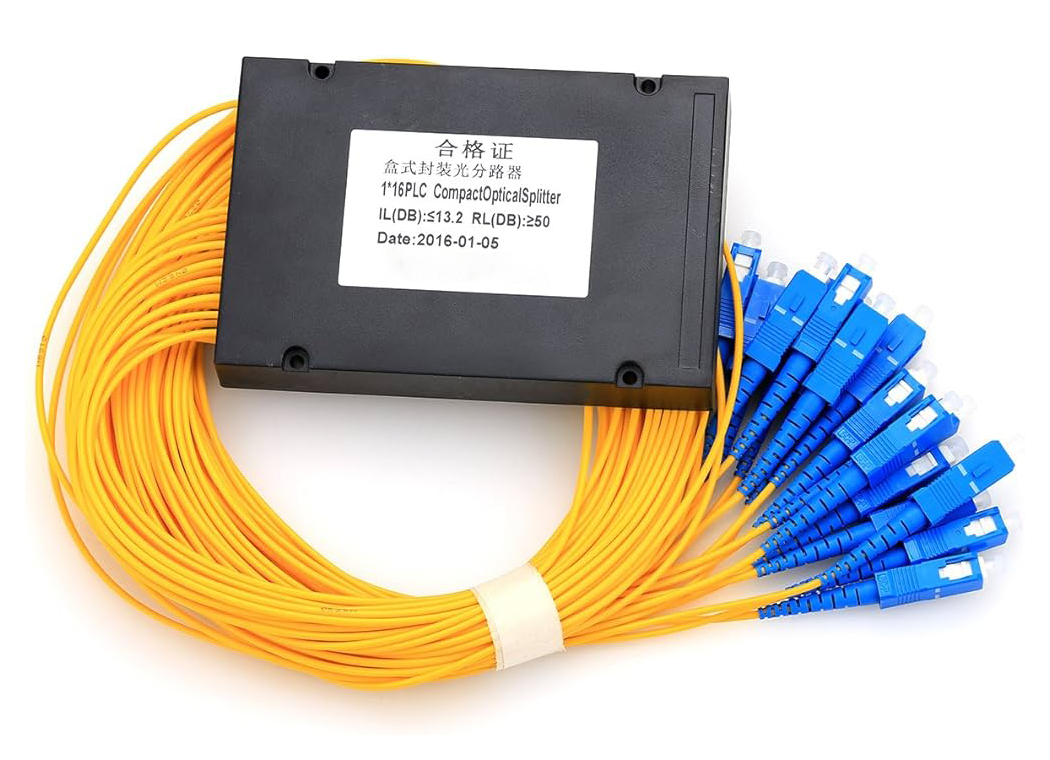
- 1×16 PLC Splitter: Common in modern deployments; loss ~13 dB.
- 1×32 PLC Splitter: High-split for dense FTTH; serves 32 homes; loss ~17 dB.
- 1×64 PLC Splitter: Ultra-high-split for large-scale PON; serves 64 homes; loss ~20 dB.
Higher ratios like 1×128 exist for specialized applications.
Even-split (equal power) is standard; uneven-split (e.g., 90/10 for monitoring) is available.
3.2 By Packaging Type
- Bare Fiber PLC Splitter: Chip only; lowest cost, for splicing.
- Blockless/Mini Module: Steel tube; compact for closures.
- ABS Box PLC Splitter: Rugged cassette with connectors; most popular.
- LGX/Rack-Mount: For ODF integration.
- Cassette/Tray: Slide-in for patch panels.
ABS box with SC/APC is the most common for FTTH optical PLC splitter deployments.
3.3 By Connector Type
- Connectorized (SC/LC/FC APC/UPC)
- Non-connectorized (bare fiber for splicing)
3.4 By Fiber Type
- Single-mode (G.657A2 bend-insensitive standard)
- Multimode (rare for PLC)
Dekam Fiber offers all configurations with custom split ratios and packaging.
4. Performance Specifications and Industry Standards
4.1 Key Optical Metrics
- Insertion Loss: 1×2 PLC splitter ~3.5 dB, 1×4 PLC splitter ~7 dB, 1×8 PLC splitter ~10 dB, 1×32 PLC splitter ~17 dB, 1×64 PLC splitter ~20 dB.
- Uniformity: ≤0.8 dB (premium).
- Return Loss: ≥55 dB UPC, ≥60 dB APC.
- PDL: ≤0.3 dB.
- Directivity: ≥55 dB.
- Wavelength Range: 1260–1650 nm.
4.2 Environmental and Mechanical
- Temperature: –40°C to +85°C
- Humidity: 95% RH
- Tensile: ≥50 N
4.3 Compliance Standards
- Telcordia GR-1209/GR-1221
- IEC 61753
- RoHS
Dekam Fiber splitters achieve premium Grade B performance with uniformity <0.5 dB.
5. Applications of Fiber Optic PLC Splitters
5.1 FTTH and PON Networks
Primary use: 1×8 PLC splitter, 1×32 PLC splitter, 1×64 PLC splitter in ODF or termination boxes for GPON/XGS-PON/50G-PON.
5.2 Data Centers
1×2 PLC splitter for monitoring taps; MPO-integrated for parallel optics.
5.3 CATV and Broadband
1×4 PLC splitter for signal distribution.
5.4 Telecom Backbone
High-count for feeder splitting.
5.5 Industrial and FTTx
Rugged ABS box for harsh environments.
6. How to Choose the Right PLC Splitter for Your Project
Choosing the optimal fiber optic PLC splitter requires careful consideration of several factors to ensure performance, cost-efficiency, and future scalability.
6.1 Determine Split Ratio Based on Network Design
- 1×2 PLC Splitter atau 1×4 PLC splitter: Small networks, monitoring, or redundancy.
- 1×8 PLC Splitter: Legacy GPON or small MDUs.
- 1×16 PLC Splitter: Balanced for modern deployments.
- 1×32 PLC Splitter: Dense urban FTTH (32 users per fiber).
- 1×64 PLC Splitter: High-split rural or large-scale PON (64 users per fiber).
Higher splits reduce fiber count but increase insertion loss—balance with OLT power budget.
6.2 Select Packaging Type for Deployment Environment
- Bare Fiber or Blockless: For splicing in closures (lowest cost).
- ABS Box: Rugged, connectorized for field installation.
- Rack-Mount/LGX: For ODF in headends.
6.3 Consider Connector and Polish Type
- SC/APC for PON (green, angled for low reflection).
- LC for high-density data centers.
- UPC for multimode or non-PON.
6.4 Evaluate Performance Grade
- Grade B (standard): Uniformity ≤0.8 dB.
- Premium/Grade A: Uniformity ≤0.5 dB for critical links.
6.5 Factor in Environmental Requirements
- Indoor: Standard ABS box.
- Outdoor: IP68-rated with UV protection.
6.6 Plan for Future Expansion
Choose slightly higher capacity (e.g., 1×32 PLC splitter instead of 1×16) for dark fiber.
Dekam Fiber offers expert consultation for custom selection.
7. Quality Control, Testing, and Common Myths About PLC Splitters
7.1 Rigorous Quality Control in Manufacturing
Premium fiber PLC splitters undergo:
- 100% insertion loss, return loss, and uniformity testing.
- Endface inspection (IEC Grade A/B).
- Environmental stress testing (temperature cycling, humidity).
- Mechanical testing (pull, vibration).
Dekam Fiber implements multi-stage QC with automated testing equipment.
7.2 Key Testing Parameters
- Insertion Loss: Measured per port.
- Uniformity: Max-min difference across outputs.
- Return Loss: Critical for PON.
- PDL and Directivity: For high-speed links.
7.3 Common Myths and Misconceptions
Myth 1: “All PLC splitters are the same”
Reality: Quality varies dramatically—premium brands achieve 0.5 dB better uniformity.
Myth 2: “Higher split ratio always means worse performance”
Reality: Modern 1×64 PLC splitter from top manufacturers has excellent uniformity.
Myth 3: “FBT splitters are better for low ratios”
Reality: PLC offers superior wavelength and temperature stability even for 1×2 PLC splitter.
Myth 4: “Connectorized splitters add too much loss”
Reality: Premium connectors add <0.2 dB.
Myth 5: “PLC splitters are fragile”
Reality: Rugged ABS packaging withstands field conditions.
Understanding these myths helps buyers avoid low-quality products.
8. Innovations and Trends 2026–2030
- Ultra-low-loss PLC for 100G-PON.
- Integrated WDM + splitter modules.
- Smart monitoring splitters.
- Sustainable manufacturing.
Dekam Fiber invests in next-gen PLC technology.
Kesimpulan
Fiber optic PLC splitters are essential for efficient PON.
Dekam Fiber offers premium PLC splitters — contact us.

